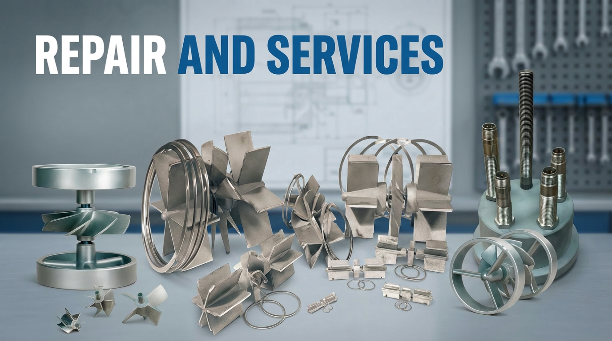
Professional Meter Repair & Calibration
Wagner Flow provides complete turbine flow meter repair and calibration services. Send us your used meter bodies and totalizers for a professional overhaul and get them back performing like new.
Contact for QuoteDIY Repair Kits
Prefer to handle repairs yourself? We stock complete repair kits for all Wagner Flow meter models with everything you need for a professional rebuild.
Shop Repair KitsTechnical Resources
Reference charts, specifications, and installation guides for Wagner Flow turbine meters
| Size | GPM | BPM | BPD | LPM | M³/D | Pulses/Gal | Max Pulses/Sec | |
|---|---|---|---|---|---|---|---|---|
| Inch | MM | |||||||
| 3/8" | 10 | 0.3 – 3 | 0.007 – 0.07 | 10 – 100 | 1.14 – 11.36 | 1.6 – 16 | 22,000 | 1,100 |
| 1/2" | 13 | 0.75 – 7.5 | 0.01 – 0.17 | 25 – 250 | 2.84 – 28.39 | 4 – 40 | 14,500 | 1,815 |
| 3/4" | 19 | 2 – 15 | 0.05 – 0.33 | 68 – 515 | 7.57 – 56.78 | 11 – 80 | 2,950 | 740 |
| 7/8" | 22 | 3 – 30 | 0.07 – 0.71 | 100 – 1,000 | 11.36 – 113.56 | 16 – 160 | 2,350 | 1,175 |
| 1" | 25 | 5 – 50 | 0.11 – 1.19 | 170 – 1,700 | 18.93 – 189.27 | 27 – 270 | 900 | 750 |
| 1-1/2" | 38 | 15 – 180 | 0.35 – 4.3 | 515 – 6,000 | 56.78 – 681.35 | 80 – 1,100 | 325 | 975 |
| 2" | 51 | 40 – 400 | 0.9 – 9.3 | 1,300 – 13,000 | 151 – 1,514 | 210 – 2,100 | 55 | 365 |
| 3" | 76 | 60 – 600 | 1.4 – 14.3 | 2,100 – 21,000 | 227 – 2,271 | 320 – 3,200 | 57 | 570 |
| 4" | 102 | 100 – 1,200 | 2.4 – 28.5 | 3,400 – 41,000 | 380 – 4,542 | 545 – 6,541 | 30 | 600 |
| 6" | 152 | 200 – 2,500 | 4.7 – 60 | 6,800 – 86,000 | 757 – 9,464 | 1,090 – 13,628 | 7 | 290 |
| 8" | 203 | 350 – 3,500 | 8.3 – 83 | 12,000 – 120,000 | 1,325 – 13,250 | 1,907 – 19,078 | 3 | 175 |
| 10" | 550 | 550 – 5,500 | 13 – 130 | 19,000 – 180,000 | 1,892 – 18,926 | 2,725 – 27,255 | 1.6 | 147 |
Note: Flow ranges shown are for standard viscosity fluids. Contact us for high-viscosity applications or extreme temperature conditions.
Material Specifications
- Flow Meter Body 316 S.S. or A-286 Alloy
- Support Vanes 316 Stainless Steel
- Rotor CD4MCu
- Sleeve Bearings Tungsten Carbide
- Shaft Tungsten Carbide
- Thrust Ball Ceramic
Performance Specifications
- Repeatability ±0.1% of indicated flow
- Accuracy ±1% of reading
- 3/8" Meter Accuracy ±2%
- Operating Temp -40°F to 250°F
- Max Pressure Up to 6,170 PSI
Tungsten Carbide Advantage: Our sleeve bearings and shafts use tungsten carbide for exceptional wear resistance and long service life, even in abrasive fluid conditions.
Maximum allowable working pressures for carbon steel flanges per ASME B16.5. Pressure ratings decrease as operating temperature increases.
| Flange Class | @ 100°F | @ 200°F | @ 400°F | @ 600°F |
|---|---|---|---|---|
| Class 150 | 285 PSI | 260 PSI | 200 PSI | 140 PSI |
| Class 300 | 740 PSI | 675 PSI | 635 PSI | 550 PSI |
| Class 600 | 1,480 PSI | 1,350 PSI | 1,270 PSI | 1,095 PSI |
| Class 900 | 2,220 PSI | 2,025 PSI | 1,900 PSI | 1,640 PSI |
| Class 1500 | 3,705 PSI | 3,375 PSI | 3,170 PSI | 2,735 PSI |
| Class 2500 | 6,170 PSI | 5,625 PSI | 5,280 PSI | 4,560 PSI |
Important: The class number does NOT equal PSI rating. A Class 150 flange is rated for 285 PSI at 100°F, not 150 PSI. Always verify your operating conditions before selection.
1 Straight Pipe Requirements
- Upstream: Maintain 15-20 pipe diameters of straight pipe before the meter (including strainer length)
- Downstream: Maintain 5 pipe diameters of straight pipe after the meter
- Multiple Elbows: If two elbows exist in different planes upstream, increase to 25+ diameters or use a flow straightener
- Flow Conditioners: Can reduce upstream requirements to 10 diameters when space is limited
2 Meter Orientation & Mounting
- Horizontal Installation: Install the meter body horizontally with the rotor assembly vertical for optimal bearing life
- Flow Direction: Always verify the flow arrow on the meter body matches your flow direction
- Flange Torque: Tighten bolts evenly in a cross pattern. Do not over-torque as this can distort the meter body
- Thread Connections: Use appropriate thread sealant. Do not use PTFE tape on tapered NPT threads for high-pressure applications
3 Strainer Requirements
- Always Use a Strainer: Install a strainer upstream to protect the turbine rotor and bearings from debris
- Mesh Size: 40-80 mesh is typical for clean fluids; coarser mesh for viscous fluids
- Maintenance: Regularly inspect and clean strainers to prevent flow restriction
- Position: Include strainer length in your upstream straight pipe calculation
4 Avoiding Common Issues
- Air/Gas Pockets: Ensure the pipe is full of liquid. Air bubbles cause erratic readings and bearing wear
- Pulsating Flow: Avoid installing downstream of reciprocating pumps. Use pulsation dampeners if unavoidable
- Cavitation: Maintain adequate back pressure to prevent vapor formation, especially with volatile liquids
- Electrical Interference: Route signal cables away from VFDs, motors, and high-voltage lines. Use shielded cable when possible
Need Help? Our technical team is available to review your installation design. Call us at (432) 214-2045 or email sales@wagnerflow.com
Complete instructions for removing worn internals and installing new repair kits. Select your meter size range below:

Exploded view: 3/8" thru 3" turbine meter internal components
Kit Removal
- Remove magnetic pickup by loosening lock nut using 3/4" thin wall socket, then unscrew from meter body. This procedure will help prevent pickup damage during the repair procedure.
- Remove snap ring from each end of meter body, using pick or screwdriver.
- Remove upstream and downstream vanes, tapping with soft rod if necessary to drive out vanes.
- Remove rotor from body.
- Clean the meter body bore as required bringing it back to a like new condition.
- Clean snap ring grooves to allow the ring to properly seat.
Kit Installation
- Install downstream vane so arrow on vane corresponds with directional arrow on the meter body. The vane blade with the notch goes between the weld stake pins.
- Install outer downstream snap ring.
- Install rotor being sure the arrow is properly aligned, and the shaft seated in the vane bushing.
- Install upstream vane, with notched vane blade between weld stake pins. Spin the rotor to allow shaft to easily enter the vane bushing. Do not use force to push the vane bearing over the rotor shaft.
- Install upstream outer snap ring.
- Make sure the rotor spins freely before installing the meter.
- Attach plastic calibration tag around the conduit hub and cut off excess strap length flush with tag.
- Install magnetic pickup: Clean pickup hub threads and pickup threads as needed. Screw in the pickup by hand until it bottoms out, then back off 1/4 turn and tighten lock nut with 3/4" thin wall socket.
Key Components

Exploded view: 4" & Up turbine meter internal components
Kit Removal
- Remove magnetic pickup by loosening lock nut using 3/4" thin wall socket, then unscrew from meter body. This procedure will help prevent pickup damage during the repair procedure.
- Remove snap ring from each end of meter body, using pick or screwdriver.
- Remove upstream and downstream vanes, tapping with soft rod if necessary to drive out vanes.
- Remove inner snap rings and rotor from body.
- Clean the meter body bore as required bringing it back to a like new condition.
- Clean snap ring grooves to allow the ring to properly seat.
Kit Installation
- Install downstream inner snap ring.
- Install downstream vane so arrow on vane corresponds with directional arrow on the meter body. The vane blade with the notch goes between the weld stake spots.
- Install outer downstream snap ring.
- Install rotor being sure the arrow is properly aligned, and the shaft seated in the vane bushing.
- Install upstream inner snap ring.
- Install upstream vane, with notched vane blade between weld stake spots. Spin the rotor to allow shaft to easily enter the vane bushing. Do not use force to push the vane bearing over the rotor shaft.
- Install upstream snap ring.
- Make sure the rotor spins freely before installing the meter.
- Attach plastic calibration tag around the conduit hub and cut off excess strap length flush with tag.
- Install magnetic pickup: Clean pickup hub threads and pickup threads as needed. Screw in the pickup by hand until it bottoms out, then back off 1/4 turn and tighten lock nut with 3/4" thin wall socket.
Key Components (4" & Up)

Exploded view: Between Flange & Ring Joint meter internal components
Kit Removal
- Remove magnetic pickup by loosening lock nut using 3/4" thin wall socket, then unscrew from meter body. This procedure will help prevent pickup damage during the repair procedure.
- Remove socket cap screws from both ends of meter using hex key.
- Remove upstream and downstream vanes, tapping with soft rod if necessary to drive out vanes.
- Remove rotor from body.
- Clean the meter body bore as required bringing it back to a like new condition.
- Clean screw holes and counter bore for vane to allow the vane to properly seat.
Kit Installation
- Install downstream vane so arrow on vane corresponds with directional arrow on the meter body. The directional arrow and notch on the vane should align with the top of the meter body, where the conduit hub is located.
- Install the downstream socket head cap screws.
- Install rotor being sure the arrow is properly aligned, and the shaft seated in the vane bushing.
- Install upstream vane, aligning the vane the same as the downstream vane. Spin the rotor to allow shaft to easily enter the vane bushing. Do not use force to push the vane bearing over the rotor shaft.
- Install upstream socket head cap screws.
- Make sure the rotor spins freely before installing the meter.
- Attach plastic calibration tag around the conduit hub and cut off excess strap length flush with tag.
- Install magnetic pickup: Clean pickup hub threads and pickup threads as needed. Screw in the pickup by hand until it bottoms out, then back off 1/4 turn and tighten lock nut with 3/4" thin wall socket.
Key Components (Between Flange & Ring Joint)
Need a Repair Kit? Browse our Repair Kits collection to find the right kit for your meter size.
Pressure drop is the difference in pressure between the inlet and outlet of a flow meter. Understanding pressure drop helps ensure your system has adequate pressure to maintain proper flow through the meter and downstream equipment. Values shown are approximate at maximum rated flow for water-like viscosity fluids.
Pressure Drop vs. Flow Rate by Meter Size
Chart shows approximate pressure drop across turbine flow meters. Actual values may vary based on fluid viscosity and specific gravity.
| Meter Size | Max Flow (GPM) | Pressure Drop Range | Notes |
|---|---|---|---|
| 3/8" | 3 GPM | 0.01 - 0.05 PSI | Lowest drop due to small flow volume |
| 1/2" | 7.5 GPM | 0.05 - 0.1 PSI | - |
| 3/4" | 15 GPM | 0.2 - 0.5 PSI | - |
| 7/8" | 30 GPM | 0.1 - 0.3 PSI | - |
| 1" | 50 GPM | 0.1 - 0.2 PSI | - |
| 1-1/2" | 180 GPM | 0.1 - 0.2 PSI | - |
| 2" | 400 GPM | 0.15 - 0.25 PSI | Most popular size |
| 3" | 600 GPM | 0.15 - 0.25 PSI | - |
| 4" | 1,200 GPM | 0.05 - 0.1 PSI | Large bore, low restriction |
| 6" | 2,500 GPM | 0.03 - 0.07 PSI | - |
| 8" | 3,500 GPM | 0.03 - 0.05 PSI | - |
| 10" | 5,500 GPM | 0.02 - 0.05 PSI | Lowest restriction |
Factors Affecting Pressure Drop
- Flow Rate Increases with flow squared
- Fluid Viscosity Higher viscosity = more drop
- Fluid Density Heavier fluids = more drop
- Meter Condition Debris increases resistance
Why Pressure Drop Matters
- System Sizing Include in pump calculations
- Cavitation Too much drop = vapor formation
- Energy Cost Higher drop = more pump energy
- Accuracy Proper pressure = accurate readings
Design Tip: Turbine meters have very low pressure drop compared to positive displacement meters. At typical operating flows (50-70% of max), pressure drop is often less than half the values shown above. For critical applications or high-viscosity fluids, contact us for detailed pressure drop calculations.
Understanding signal types is essential for properly integrating your flow meter with totalizers, PLCs, and SCADA systems. Here's what you need to know:
Pulse Output (Frequency)
- How It Works AC sine wave from coil
- Signal Source Magnetic pickup
- Output Pulses/gallon
- Best For Totalizing, batch control
- Max Distance 100-500 ft typical
- Power Required None (self-generating)
4-20mA Analog Output
- How It Works Current loop signal
- Signal Source Transmitter/converter
- Output 4mA=0%, 20mA=100%
- Best For PLC/SCADA, rate display
- Max Distance 2,000+ ft
- Power Required Loop or external
Digital (Modbus RTU)
- How It Works Serial communication
- Signal Source Flow computer
- Output Multiple values
- Best For Complex systems, logging
- Max Distance 4,000 ft (RS-485)
- Power Required External power
? Which Signal Type Do I Need?
- Simple Totalization: Use pulse output directly to a totalizer - no converter needed
- Flow Rate to PLC: Add a 4-20mA converter or use a totalizer with 4-20mA retransmit
- Long Cable Runs: 4-20mA is more noise-immune over distance than pulse
- Multiple Data Points: Digital Modbus provides rate, total, and diagnostics in one connection
- Battery Applications: Pulse output requires no external power
Common Setup: Most customers use a magnetic pickup (pulse output) connected to an EDD-800 totalizer, which can then retransmit 4-20mA to a PLC if needed. This gives you local display plus automation capability.
Selecting the right totalizer depends on your environment, input/output requirements, and any hazardous area classifications.
| Model | Area Rating | Inputs | Outputs | Best For |
|---|---|---|---|---|
| EDD-800 (F012) | Safe Area / IS | Pulse, 4-20mA | 4-20mA, Pulse | General purpose |
| EDD-810 (F110) | Safe Area / IS | Pulse, 4-20mA | 4-20mA, Pulse, Relay | Alarms, batching |
| EDD-818 (F018) | Safe Area / IS | Pulse, 4-20mA | 4-20mA, HART | HART integration |
| EDD-E18 (E018) | Explosion Proof | Pulse, 4-20mA | 4-20mA, Relay | Class I Div 1 |
| EDD-E10 (E110) | Explosion Proof | Pulse, 4-20mA | 4-20mA, Pulse, Log | Logging in hazloc |
Intrinsically Safe (IS)
- Area Class Class I, Division 2
- Protection Limited energy
- Enclosure Aluminum or 316SS
- Approvals ATEX, IECEx, FM, CSA
- Cost Lower
Explosion Proof (Ex d)
- Area Class Class I, Division 1
- Protection Contains explosion
- Enclosure Heavy-duty Ex d
- Approvals ATEX, IECEx, CSA
- Cost Higher
! Division 1 vs Division 2 Explained
- Division 1: Hazardous gases/vapors are present during normal operations (e.g., inside a tank, at a wellhead)
- Division 2: Hazardous gases/vapors only present during abnormal conditions (e.g., pipe leak, equipment failure)
- Safe Area: No hazardous gases expected - standard equipment is acceptable
- When in Doubt: Consult your facility's area classification drawings or safety engineer
Cross-Reference Note: EDD part numbers correspond to Fluidwell models (shown in parentheses). Same quality Dutch-manufactured units with local support. Looking for a specific Fluidwell model? Contact us for cross-reference help.
1 Entering Programming Mode
- Press and hold the SET button for 3 seconds
- Display will show "P01" indicating programming mode
- Use arrow buttons to navigate between parameters
2 Setting the K-Factor
- Navigate to the K-Factor parameter (typically P02 or P03)
- Enter the pulses per gallon value from your meter's calibration tag
- Press SET to confirm each digit
- Example: A 2" meter typically has a K-factor of 55 pulses/gallon
3 Setting Units & Decimal Point
- Select your desired flow units (gallons, barrels, liters, etc.)
- Set decimal point position based on your measurement precision needs
- Configure rate display (GPM, BPH, etc.) if applicable
4 Exiting & Saving
- Navigate past the last parameter or press SET on the exit option
- Settings are automatically saved to non-volatile memory
- Power cycle the unit to verify settings are retained
K-Factor Reference: Your meter's specific K-factor is printed on the calibration tag attached to the meter body. Always use the exact value from your specific meter for best accuracy.
Flange Standards
- ASME B16.5 Pipe flanges ≤24"
- ASME B16.47 Large diameter flanges
- API 6A Wellhead equipment
Flow Measurement
- API MPMS Ch. 5 Metering standards
- API MPMS Ch. 5.3 Turbine meters
- AGA Report No. 7 Turbine measurement
Looking for Specific Standards? Contact our team and we can help you find the right documentation for your application or compliance requirements.
Need Assistance?
Phone: (432) 214-2045
Email: sales@wagnerflow.com